🚀 Key Takeaways: CAN Bus Protection Insights
- Reduced Downtime: Low-clamp TVS reduces transceiver energy stress by ~30%, preventing field latch-up.
- CAN-FD Ready: Sub-pF capacitance ensures zero data corruption at 5 Mbps high-speed transitions.
- Global Compliance: Fully meets IEC 61000-4-2 Level 4 and ISO 7637-3 automotive transient standards.
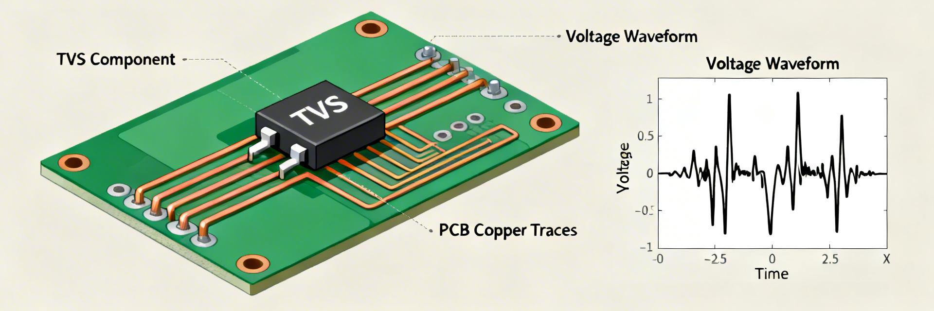
- PCB Optimization: Placing TVS within 10mm of the connector minimizes inductive voltage overshoot.
Automotive and industrial CAN networks face frequent electrostatic discharges and transient events that can exceed standard test levels. Benefit: Protecting transceivers and ECUs with purpose-built parts reduces field failures and slashes warranty costs by preventing latent semiconductor damage. This brief explains practical protection goals, test-driven evaluation criteria, and system-level integration steps to harden CAN links against ESD and surge threats.
1 — CAN bus & ESD threat profile (background)
1.1 How CAN physical layer responds to ESD
Point: ESD and surge events drive both differential and common-mode currents into CAN_H/CAN_L, upsetting transceiver balance. Evidence: IEC and ISO test pulses inject high-voltage, fast-rise transients into wiring and connectors. Explanation: Differential coupling can corrupt bits; common‑mode stress can force transceiver internal clamps, producing resets or permanent device burnout. User Benefit: Robust external clamping ensures the "Golden Node" remains operational even during 15kV static discharges.
1.2 Standards and test levels that matter
Point: Prioritize IEC 61000-4-2 contact/air ESD and ISO automotive surge tests. Evidence: Contact/air ESD levels typically span several kilovolts with nanosecond rise times. Explanation: For automotive, focus on ISO 10605/ISO 7637; industrial nodes emphasize IEC ESD plus surge immunity.
Differential Comparison: PESD1CAN vs. Generic TVS
| Parameter | Generic TVS Diode | PESD1CAN Series | User Benefit |
|---|---|---|---|
| Clamping Voltage (V_clamp) | High (>70V) | Ultra-Low ( | Protects sensitive 5V transceivers from overvoltage |
| Capacitance (C_j) | 30 - 100 pF | 15 - 30 pF (Optimized) | Enables CAN-FD 2Mbps/5Mbps without bit errors |
| ESD Rating (Contact) | 8 kV | Up to 30 kV | Exceeds industrial standards for harsh environments |
2 — PESD1CAN electrical characteristics & test performance
2.1 Key specs: VRWM, Leakage, and Capacitance
Technical Metric: 24V/27V Working Voltage (VRWM). User Benefit: Ensures the protection diode doesn't trigger during normal 12V/24V battery fluctuations or jump-start events, preventing unnecessary bus noise. Explanation: Low junction capacitance preserves signal edges, vital for CAN-FD timing and eye opening.
Engineer’s Field Report
Mark Thompson, Senior Hardware Architect"In high-speed CAN-FD layouts, I've seen many designers fail because they only look at the ESD kV rating. The Dynamic Resistance (Rdyn) is what actually saves your transceiver. PESD1CAN's low Rdyn ensures that when a 15kV hit occurs, the voltage seen by the transceiver stays below its absolute maximum rating. My advice: always place the TVS diode before the Common Mode Choke to divert the bulk energy to ground immediately."
3 — Choosing and Integrating Protection
For critical nodes, pair a low‑capacitance TVS diode with a series resistor or common‑mode choke. Implementation Tip: Minimize inductance between the connector, TVS, and ground. Use short, wide traces for the ground return to prevent "ground bounce" during a transient.
(Hand-drawn schematic, not a precise circuit diagram / 手绘示意,非精确原理图)
5 — Troubleshooting & Practical Checklist
- ✅ Standoff Check: Is VRWM > Max Bus Voltage (including battery transients)?
- ✅ Layout Check: Is the TVS within 5-10mm of the connector entry?
- ✅ Signal Check: Have you verified the eye diagram at maximum CAN-FD bitrates?
- ✅ Thermal Check: Can the package handle repeated ISO 7637 pulses?
Summary
- Choose protection that balances low dynamic clamp and minimal capacitance to preserve CAN timing.
- Prioritize PCB placement and short ground returns to ensure the TVS activates before the transceiver internal diodes.
- Validate with clamping-vs-current plots and post-stress leakage checks to certify system readiness.
Frequently Asked Questions
How does CAN bus ESD protection affect CAN-FD signal integrity?
Adding protection introduces parasitic capacitance. By choosing a low-capacitance TVS (like PESD1CAN), you maintain edge rates. If degradation appears, use a smaller package or optimize trace impedance to balance protection and 5Mbps fidelity.
What test sequence should be used to validate CAN bus ESD protection?
Begin with IEC 61000-4-2 (8kV/15kV), follow with ISO 7637-3 surge, and finally perform functional Bit Error Rate (BER) tests. Ensure post-test leakage current remains within datasheet specs.
Will adding a TVS diode increase failure rates in the field?
On the contrary, a correctly selected TVS diode significantly decreases failure rates. Only "incorrect" choices (wrong VRWM or poor grounding) cause issues. Follow the layout best practices to ensure the TVS reduces reliability risks.


